CFD
Simulating Computational Fluid Dynamics
Magna is offering a wide range of simulation services in the automotive industry. 3D simulation can support you in improving your system or your component regarding thermal or flow related aspects by understanding a certain behaviour at a stage where measurements are not yet possible, or by looking into detail where measurements cannot be done.
Within the thermal management department simulation capabilities are covering 3D fluid simulation (CFD and SPH) and 1D system simulation related to thermal systems.
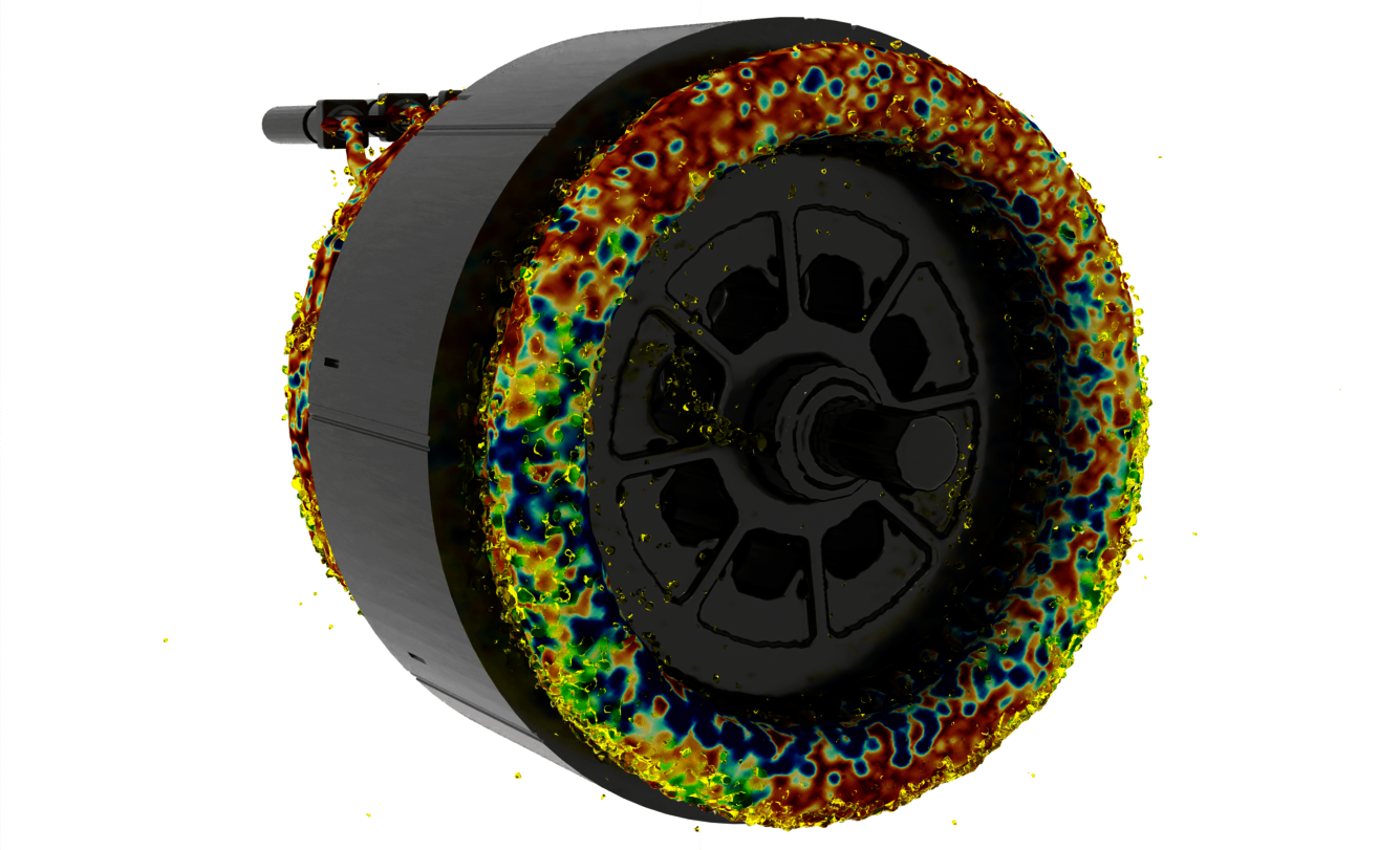
Computational fluid dynamics (CFD) plays an essential role in vehicle thermal management (VTM) as there are different sort of fluids contributing to the overall behaviour of single components as well as of the whole vehicle. 1D system simulation (using KULI) brings the fluids together by looking at the interaction between different cooling circuits inside a vehicle. The method of smooth particle hydrodynamics (SPH) was established in the last few years and is used in addition where conventional CFD comes to its limits, e.g. for complex oil-air phase interactions.

Computational fluid dynamics means
- Understanding fluid flows inside your components
- Predicting flow behaviour where measurement sensors cannot be applied
- Reducing development costs by introducing simulation loops in the development process
- Improving and optimizing your designs
- Supporting the design process with a virtual data base for certain components (e.g. performance map)
CFD simulation for full vehicle simulations
On a full vehicle level, accurate prediction of the air flow allows you to improve the aerodynamic performance. Especially for truck applications the reduction in drag is one of the drivers to decrease fuel consumption. At the Engineering Center Steyr (ECS) a close communication between cabin design and thermal management department allows to efficiently develop aerodynamic well shaped as well as technical feasible designs of state-of-the-art cabins. Moreover, cabin soiling improvements are implemented by visualizing the water droplet flow field on the areas of interest using CFD.
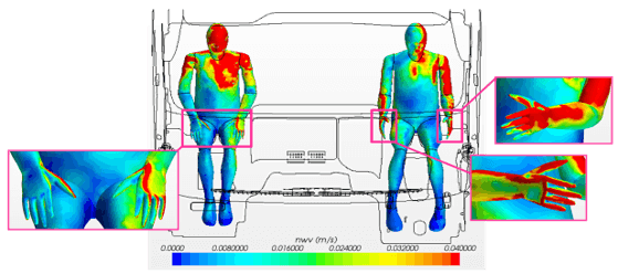
In cabin development not only visualization of flow around, but also inside the cabin helps to design HVAC ducts efficiently. Also, the physics of melting of ice layer through warm air in the de-icing ducts can be captured well, which helps to prove the defined regularizations. Further if a passenger feels comfortable during driving or not, can be already investigated in an early development phase.

Looking at the powertrain, vehicle thermal management (VTM) is the glue which sticks the components together via cooling circuits and which ensures that the whole drivetrain is not restricted by any thermal issues. For this, CFD simulation of the engine compartment gives a deep insight how the air mass flow takes away the heat generated by the powertrain components. Improving the cooling package performance by maximizing the air mass flow through it and in parallel minimizing recirculation paths is something where simulation strongly supports the development process. Combining 3D simulation results with our full vehicle system simulation based on KULI, coolant temperatures can be predicted accurately resulting in feedback for further optimization loops in 3D simulation.
CFD simulation for virtual product development
On a component level 3D CFD simulation gives you a detailed insight how your component is working and how it`s thermal behaviour of your component will be affected by several design changes. Using simulation in an early stage allows you to start with a well investigated prototype instead of doing several tests to overcome the issues from the very first design. Moreover, understanding the physical behaviour of the fluid inside the component helps you to strengthen your experience for the respective component.

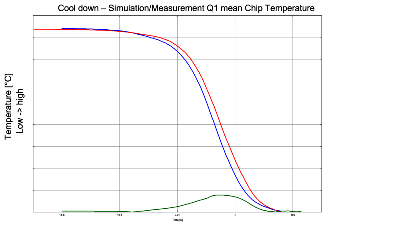
We are focussing on components in the powertrain. There is a deep knowledge for inverter, e-motors and gearboxes at Magna’s locations in Austria that offer testing facilities including applications and validated simulation models. Questions to be answered are typically the distribution of heat fluxes from the heat source (e.g., dies, winding heads) to the sink (coolant, oil). In case of finding the optimal cooling structure we are applying optimization algorithms to get the most out of your design.

CFD Simulation Services by Magna ECS
- Design optimization with respect to aerodynamics and soiling
- Virtual cooling package integration by means of underhood and cooling system simulation
- Underhood heat protection for optimal component arrangement
- Cabin comfort investigations including cool-down, heat up and de-icing simulations
- Oil flow distribution inside components
- Conjugate heat transfer simulations for component design development

